
Defining connections
We’re down to the last part of this tutorial. There’s one more important concept left to handle, namely connections. In general, components interact with each other via a connection, specifically a row connection. I’m sure you’re familiar with the different types, such as “Main”, “Reject”, “Output”, “Lookup”, … When defining such connections for your custom component, you’ll have to use a connector. We’re mainly going to focus on a specific type of connector, called a flow connector. This connector allows data to flow in and/or out of a component.
When it comes to data processing, components are divided in three different categories:
- Input components: These components only have outgoing connections.
- Output components: These components only have incoming connections.
- Processing components: These components have both incoming and outgoing connections.
Usually you already know which category applies to your component. Based on that fact, you can easily define the necessary settings for it.
Let’s take a look at our XML descriptor file. You’ll notice that a connector is already present, namely within the CONNECTORS tag:
<CONNECTORS>

<CONNECTOR CTYPE="FLOW"/>

</CONNECTORS>
Connectors are defined in an inner tag called CONNECTOR. For this specific tag you can define attributes, one being of the utmost importance when it comes to defining a connector, namely CTYPE. This attribute is used to specify the type of connector. Of course there are different types of connectors available and it’s possible to define multiple connectors in general. However, there should only be one connector per type. In our case the value “FLOW” is set, to indicate that the connector has to be a flow connector. This is exactly what we wanted in the first place. For each type of connector, you can define optional attributes. The most important optional attributes are the following:
- MIN_INPUT: This attribute allows you to specify the minimum number of permitted input instances for the connector.
- MAX_INPUT: This attribute allows you to specify the maximum number of permitted input instances for the connector.
- MIN_OUTPUT: This attribute allows you to specify the minimum number of permitted output instances for the connector.
- MAX_OUTPUT: This attribute allows you to specify the maximum number of permitted output instances for the connector.
Using these attributes, the minimum and maximum incoming and outgoing connections can be defined for the component. As stated before, these are optional. However, in the case of a flow connector, maximum input instances and maximum output instances are usually specified. Let’s go ahead and specify these attributes for our custom component. We’re going to make the component an input component, so only outgoing connections apply. Head over to the XML descriptor file and update the connector statement to the following:
<CONNECTOR CTYPE="FLOW" MAX_INPUT="0" MAX_OUTPUT="1"/>
Obviously there are no input instances and there’s just one output instance. This is only the first step in defining an input component though. Basically there’s something very important missing. If you look at the component now, we haven’t defined any input data yet nor have we defined a data structure for that input data. That means the component doesn’t know which type of data should be sent to the output. In order for this to happen, we have to define a parameter containing the schema/metadata for the output. A parameter is, as you already know, defined in the XML descriptor file. Add the following code to the file:
<PARAMETER

NAME="SCHEMA"

FIELD="SCHEMA_TYPE"

REQUIRED="true"

NUM_ROW="1">

</PARAMETER >
The field SCHEMA_TYPE takes care of the metadata. Whenever you define a schema, it’ll be automatically passed to the outgoing connections. This parameter will be added to the “Basic settings” panel. In the previous part we’ve already defined two other basic parameters, so I’d like you to adjust the NUM_ROW attributes for those parameters as well. You basically want three parameters under each other in that specific panel.
Now we’re going to write some code, which will allow us to send data to the output. As you already know, we’ve got three JET files. In the tFirstComponent_begin.javajet file we’ve got a loop defined. The content of the loop, which generates the actual data output, is defined in the tFirstComponent_main.javajet file. Each time the code in the tFirstComponent_end.javajet file is called, data’s being sent to the output connection(s). Per outgoing connection, we want to load the values for every single field contained in each record, exactly before that code is called. These fields are defined in the schema. So our next step involves writing some more code in the tFirstComponent_main.javajet file. Go to that file and start off by adding java.util.List to the imports section. I’d like to note that this file is going to change quite a bit. I recommend to override the existing code, underneath the imports section, with the next couple of code fragments. Let’s start by adding this piece of code (changes are in bold):
<%

CodeGeneratorArgument codeGenArgument = (CodeGeneratorArgument) argument;

INode node = (INode)codeGenArgument.getArgument();

String cid = node.getUniqueName();
List<IMetadataTable> metadatas = node.getMetadataList();

if ((metadatas != null) && (metadatas.size() > 0)) {

IMetadataTable metadata = metadatas.get(0);

if (metadata != null) {
In this piece of code, we get the metadata of the component, which is defined in the parameter we just added in the XML descriptor file. You’ll notice that a list of MetadataTables is present in the code. In general, it’s possible to have multiple SCHEMA_TYPE parameters, each with their own schema. In order to keep track of all of these parameters and schemas we have to put of all them in a list. Of course, in this case, there’s only one parameter. To get that specific parameter’s schema, we use the metadatas.get(0) statement.
For the next part, please add the following statement to the imports section: org.talend.core.model.process.EConnectionType. After that, paste the following code below the previously added code:
List< ? extends IConnection> outgoingConns = node.getOutgoingConnections();

for (IConnection conn : outgoingConns)

{

if (conn.getLineStyle().equals(EConnectionType.FLOW_MAIN))

{

String outputConnName = conn.getName();
In this piece of code, we put all of the outgoing connections in a list. After that we loop through them in order to get the name of the outgoing row<number> connection. The name of the connection is then stored in a String variable called outputConnName. In the loop there’s an if statement as well. This statement makes sure only the “MAIN” data type connections are checked. In this case, it’s the only connection which will be used so it makes sense to only check that particular one.
Let’s add the last piece of code:
for( IMetadataColumn col : metadata.getListColumns() ) {

%>

<%=outputConnName %>.<%=col.getLabel() %> = "Row data for the <%=col.getLabel() %> column has been passed!";

<%

}

}

}

}

}

%>

System.out.println("The main section has been executed " + counter_<%=cid %> + " time(s)");
This is quite a complicated structure and it’s incredibly disordered when looking at it in different pieces. For that reason, you’ll find an image below representing the whole structure:
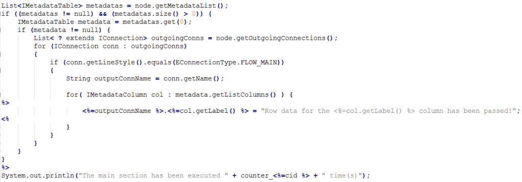
This last bit of code iterates over the columns defined in the metadata variable and writes output to the Java output code. The string inside the for loop, containing the name of a column of an input row, is assigned to an output row. The assignment is done column by column. I’ve chosen this particular string purely as an example. It’s important to note here that I assume that every single column that’s defined in the schema is a string. When printing the results to the console, you’ll notice that the same string is repeatedly printed for every column. The amount of printed lines depends entirely on the amount of processed rows. For example, if you’ve got two rows of input data you’ll see that the string is printed for each column within a particular row. Two rows containing data means two lines of output. As an extra, I’m printing the amount of times the main section gets executed. Each time it gets executed, a row is processed. This gives you a nice overview in the console window.
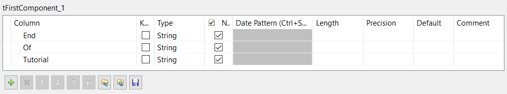
In order to test the component, you have to perform the usual steps of pushing the component to the Palette and then dragging it to the job canvas. On top of that, since the component is now an input component, you’ll have to drag a tLogRow component to the canvas as well. Finally, connect the custom component to the tLogRow component. Once that’s done, you have to define a schema for the custom component. To do that, go to its “Basic settings” and click on “Edit schema”. You can choose the schema yourself, however all columns/fields have to be strings! Below you can find my example:
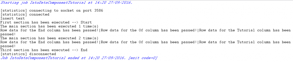
After that, go to the “Advanced settings”. Remember the first advanced parameter we defined in the previous part of this tutorial? Well, you have to give that parameter a value as well. In this particular context, the value you give to this parameter represents/simulates a certain amount of rows. So, if you give it the value 2, two fictive rows will be generated. In the background all you do is loop through the process twice. Let’s go ahead and give it that value. Now run the job! You should get the following output:
And here you go, the basics of custom component creation have been handled. I’d like to emphasize that this tutorial is just a start, something to get you going. There’s way more to it than this. The best way to learn more about this topic is to pick a random standard Talend component and check out the code in the different files belonging to that component. Thank you very much for reading this tutorial. I hope you learned a thing or two. See you soon!
Download the full tutorial here
Used sources:
- http://www.talendbyexample.com/talend-custom-component-xsd.html
- http://www.powerupbi.com/talend/componentCreation_1.html
- https://help.talend.com/display/KB/What+is+a+Talend+component
- https://help.talend.com/display/KB/How+to+create+a+custom+component
- http://www.talendbyexample.com/talend-api-for-component-designers.html
- http://bekwam.blogspot.be/2011/04/column-metadata-in-talend-open-studio.html